Kenwood TS-440S
I’ve been cutting my teeth on solid state HF radios by learning to repair and align a TS-440S. I’ve repaired half a dozen of these so far including a couple for friends.
Overview
They’re a pretty solid radio for the time. Outside of the usual unobtainable silicon parts these days and IF transformers you’d have to rewind yourself to repair, the TS-440S holds up pretty well as a repairable 1980’s HF rig.
I’ve had no issues sourcing replacement parts, including cannibalising older boards for components. However, the risk I have is that unless a radio is completely dead or disassembled, I’ve had a pretty damned good success rate at taking a broken radio and making it squeak again. As of 2018, ebay is your friend.
It sports a pair of finals transistors on a rather oversized aluminium heatsink which according to the user manual can do full keydown carrier for an hour before a 45 minute downtime. It’s quite possible with even further cooling one could run the radio for longer duty cycles. I use it quite extensively for 95W digital modes and once restored well, a TS-440S could do FT8 or JT65 for hours at a time without breaking a sweat.
Common Issues
There are a slew of websites covering a variety of TS-440S modifications and issues. I’ll start tallying some soon - but for now, here’s a shortlist of things I’ve noticed that need to be addressed.
Dry Joints
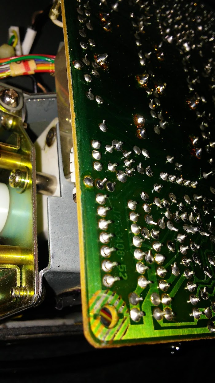
There are very likely dry joints everywhere. This seems to be some weird combination of perhaps some early automated soldering and a whole lot of a lack of solder being used. In a lot of cases I’ve seen barely enough solder on each pad and it cracks very very easily. A lot of repairs can be summarised as “take out each board, touch up every joint.”

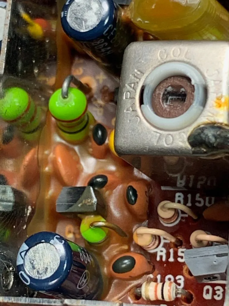
Finals
The finals are either in great shape or someone’s run the rig into the ground. I always pull out the LPF output filter and finals board for inspection. I’ll always touch up the soldering on the finals board - especially around all the transistors on the board. A fresh coat of thermal grease is also a great idea.
There’s a temperature sensor on one of the finals transistors but it isn’t physically attached to it - it’s held in place by a combination of bent leads and tucking it underneath a diode. It’s .. not always very structurally stable. I highly recommend bending the thermistor leads back more so it pushes more firmly up against the finals transistor and then tucking it under the diode.
Computer Control
Just source the two ICs - one is a CMOS logic device and the other is a UART. It’s easy to install it and it’s very easy to build a suitable cable. Note the output is inverted - making it hard to hook into a 5v FTDI chip but super easy to hook into optoisolators which then you run into the FTDI chip.
(TBD - just post a circuit diagram about it!)
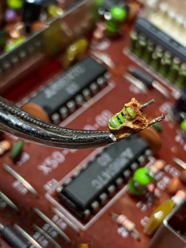
Sonybond glue on VCO1 / VCO5
Kenwood used Sonybond glue on VCO1 and VCO5 to stop components there from vibrating from things like movement (eg mobile/car mounting) and loud audio. These VCOs are so sensitive to component values that mechanical movement changes parasitic induction/capacitance and this leads to frequency drifts, causing little audible blips in the VCO frequency before the PLL re-adjusts.
Over time the glue apparently absorbed water and changes until it became this .. well, less goopy, more solid mess. It then became conductive enough to affect circuit behaviour.
The sonybond glue looks brown/yellow. It’s either thick and waxy, or it’s darker brown and brittle. The latter will start eating away at component legs so be careful.
Later on Kenwood switched to a different, more waxy looking glue. This stuff is fine. You don’t need to remove it.
The bad stuff, before it dries out:
(from https://www.w5rrr.org/2019/05/12/freds-ts-440s-repair-adventure-part-1/)
The bad stuff, once it’s dried out:
(from https://www.w5rrr.org/2019/05/12/freds-ts-440s-repair-adventure-part-1/)
The OK stuff:
VCO1 Repair/Alignment
(tbd)
VCO5 Repair/Alignment
(tbd)
RF Board Repair/Alignment
(tbd)
PLL Board Repair/Alignment
(tbd)
USB/SSB frequency response, IF offset Alignment
Here’s a fun one. If you read the service manual you’ll find there’s a section in the alignment chapter on the USB/SSB frequency response - and a set of 10 DIP switches to set. This is used to set the USB and SSB frequency response using a two-tone AF generator and a scope.
Now, what this implies is that there’s a somewhat tight coupling between the IF/RF boards that have SSB filters on them, and the control/CPU board with those DIP switches.
If they’re set wrong, then you end up with two things:
- Your frequency response is way off, and things will sound terrible on transmit/receive; and
- You won’t be able to correctly centre align the IF Offset adjustment alignment!
So if you’ve gone and switched out your IF board, (or maybe your RF board, be careful) or the Control/CPU board you will have to do this realignment. It’s not too bad - just make up a cable from your computer to the AFSK input jack (with a suitable attenuator so you don’t distort things), hook up the output to a scope via a suitable dummy load and directional coupler/attenuator and do it!
Bypassing the finals for output alignment
Whilst on the topic of output alignment - here’s something I commonly do. Unless you need to test something like the finals or ALC, you can just take the RF output from the RF board, put it into a 56 ohm resistor and put a scope across that. I’ll do this for testing things like the above USB/SSB frequency response, frequency calibration, output carrier cleanliness, modulation, etc - none of these require full output power or ALC to work. It saves a bunch of headache around things around having to output real RF power just to check things - so you don’t have to worry about how long you leave your radio on and transmitting whilst aligning the VCOs/PLLs.
Electronic hum always being present!
So this is a fun one. There’s a three-wire cable running from the IF board to under the PLL board area where the optional VS-1 (voice synthesis) unit lives. However, this isn’t a shielded or terminated wire - so it picks up all kinds of electrical noise from the PLL board if the VS-1 isn’t connected.
You can hear the electrical noise even with the volume turned down - the VS-1 level is independent of the volume control, similar to the control beeps.
I recommend getting a 56 ohm resistor and putting it between the sound and ground pins on that connector. Be sure you’re not putting it against the +ve rail pin - it’ll make the resistor unhappy. That will ground the cable a little and prevent it from being such an open-ended antenna.
AM transmit not working
Apparently AM transmit is not allowed in some countries, and one of the diodes on the control board (D77) controls it. If your rig doesn’t PTT when you try transmitting on AM, look to see if you need to clip D77.
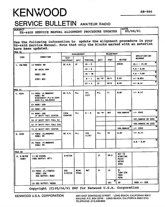
Alignment / Calibration Errata
There are some mistakes/omissions in the TS-440S alignment instructions. These are covered in the service bulletins.
-
SB-986 - Voltage, VCO3, VC4, S-Meter Calibration - this has corrections for an incorrect band setting for 13.9999MHz -> 14.0000MHz VCO (VCO3) and the IF shift offsets (VCO4).
-
ALC min/max calibration - the TS-440S calibration instructions are missing how to establish the ALC minimum and maximum values. The TS-430S ALC instructions include the missing bits - notably, calibrate ALC low as per the instructions (MIC level min, AG at 1KHz, 5mV RMS), then bump it up +6dB, verify you’re seeing 100W RF output from the finals, and then adjust IF VR-11 to maximum ALC scale reading.